


Racing the Beam
Description
Racing the Beam. Dan’s MEGA65 Digest for May 2024.
<figure>
<figcaption>
Racing the Beam.
</figcaption>
</figure>
At least once before in this Digest I’ve said something about how there’s a way to write a program to perform precisely timed actions, but the actual technique would have to wait until a future issue. In this issue, we’ll start looking into this, with a focus on synchronizing a program with a particularly useful hardware feature: the raster beam.
To do this effectively, we’ll introduce an important programming paradigm supported directly by a feature of the CPU, called interrupts. To get that to work, we’ll also take a brief look at how to uninstall the KERNAL operating system by changing the system’s memory map.
Any news?
Trenz Electronic is busily assembling new MEGA65s, still on track for delivering the next batch in the next few weeks. The Discord and Forum64 board have been quieter than usual, with everyone starting new projects or resting up from previous ones. I can’t wait for the rush of new people joining and asking questions!
If you have a project in progress that you’d like to see featured in the Digest, let me know! You can also announce your project in the #announcements channel on the Discord, and upload your work in progress to Filehost for others to try. Beginners welcome! Some of the coolest stuff we’ve seen for the MEGA65 has been written in BASIC by people like you just trying things out.
The time keepers
<figure>
<figcaption>
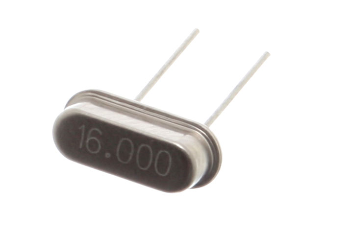
16 MHz crystal oscillator.
</figcaption>
</figure>
Every computer contains a component that generates a clock signal, a fast and precisely timed electronic pulse that drives the digital devices in the computer. Like turning the crank of a music box, these pulses advance the internal mechanisms of each device through their various stages to perform computations, and to generate signals of their own. The clock signal also synchronizes the devices with each other, so they can communicate with one another over their electronic connections.
MEGA65 programs can take advantage of three specific devices driven by the system clock to execute code with precise timing: the CPU, the VIC video chip, and the CIA chip.
The CPU
The CPU uses the clock signal to perform the machine code instructions of a program. Each instruction requires a certain number of cycles to perform, where each cycle takes a fixed amount of time based on the clock. For example, the lda #$ff instruction, which loads the byte value $ff from the program code into the accumulator register, takes two CPU cycles to complete. The cycle cost of an instruction depends on the instruction and addressing mode, but it’s typically between 1 and 6 cycles, and as many as 14 cycles for fancier operations like the 45GS02 Q-register instructions.
In its default MEGA65 mode, the MEGA65 CPU performs instructions at 40.5 million cycles per second, or 40.5 megahertz (MHz). The MEGA65 can also underclock its cycle rate to emulate a Commodore 64 (1 MHz), Commodore 128 (2 MHz), or Commodore 65 (3.5 MHz).
In theory, you can analyze the duration of a section of machine code by looking up the cycle costs of each instruction and adding them together. Commodore 64 programmers sometimes do this to optimize small sections of code, especially for advanced video effects that require precise coordination between the 1 MHz CPU and the VIC video chip. This is less necessary with the MEGA65’s 40.5 MHz CPU, which outpaces most of the signal frequencies that a program might care about.
A program can pause for a period of time by executing instructions and ignoring the results, simply to burn through cycles. This could be a series of instructions in memory, a loop with a counter, or a loop that exits when a hardware register changes. This technique is known as busy-waiting because the CPU can’t stop executing instructions: it has to twiddle its thumbs to keep busy—and also to figure out when to stop waiting and continue the program.
Try these examples of busy-waiting in BASIC:
5 REM -- PAUSE BRIEFLY BY DOING NOTHING IN A LOOP
10 BORDER 0
20 FOR A=1 TO 20000
30 NEXT A
40 BORDER 1

5 REM -- WAIT FOR JOYSTICK FIRE BUTTON, PORT 1
10 BORDER 0
20 IF (JOY(1) AND 128)=0 THEN 20
30 BORDER 1
The VIC
<figure>
<figcaption>
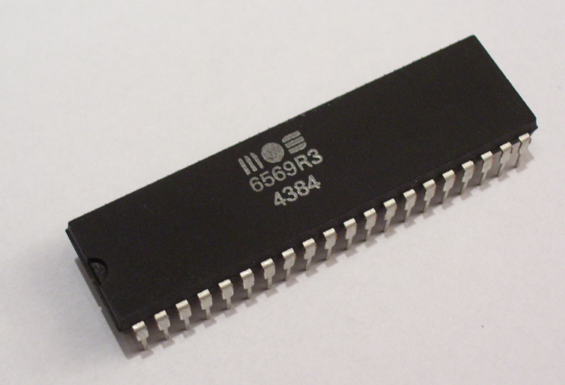
The VIC 6569 chip. (Image from c64-wiki.com)
</figcaption>
</figure>
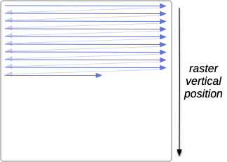
The VIC video chip uses the system clock to generate a video signal with the precise timing expected by the display hardware. Such protocols are derived from old cathode-ray tube (CRT) displays that draw the entire screen with a beam of electrons. This raster beam sweeps across the screen in a fixed pattern of horizontal rows, or raster lines, from left to right, top to bottom. The video signal controls the intensity of the beam, and the beam leaves pixels in its wake that form the complete image. Once it reaches the bottom, the beam returns to the top of the screen, and the process repeats, many times per second.
<figure>
<figcaption>
Path of the raster beam: left to right, top to bottom.
</figcaption>
</figure>
The MEGA65 connects to modern VGA analog or HDMI digital displays. Internally, it attempts to recreate the display parameters of one of two vintage analog video modes, either PAL or NTSC, so that vintage software that depends on these parameters will run properly. The PAL video mode draws 312 raster lines 50 times per second, also known as a refresh rate of 50 Hz. NTSC draws 262 lines 60 times per second, or a refresh rate of 60 Hz. A full image consists of two interlaced sets of lines, so the actual image size and frame rate is twice as many lines and half the frequency: PAL video is 625 lines tall with a frame rate of 25 Hz.
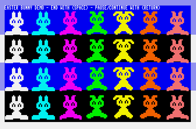
Synchronizing a program’s behavior with the raster beam is a powerful way to perform advanced visual effects. By changing VIC control parameters at specific times during the drawing of the screen, a program can break away from some of the VIC’s numerical limitations. This is the basis for one of the most coveted of Commodore graphical techniques, called sprite multiplexing, where the VIC’s eight hardware sprites are reused in different parts of a single screen.
<figure>
<figcaption>
easterbunnydemo3 by Nobato, from Intro Disk #3, demonstrating sprite multiplexing from BASIC.
</figcaption>
</figure>
The CIAs
<figure>
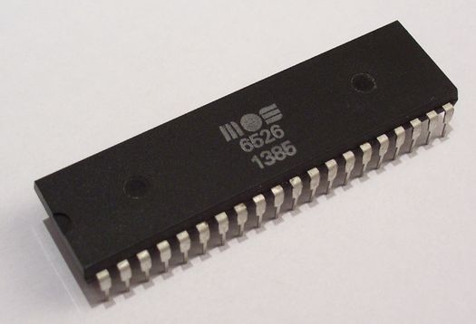
<figcaption>
The CIA 6526 chip. (Image from c64-wiki.com)
</figcaption>
</figure>
The Complex Interface Adapter (CIA) chip is a multi-purpose chip that manages device and serial communications, and also has a high-precision countdown timer feature. Each CIA chip contains two timers, and the MEGA65 (like the Commodore 64) has two CIA chips, each wired up a bit differently. The CIA counts pulses at a rate of 1 MHz, and your program can set a timer interval up to 65,535 of these pulses, for a delay of up to approximately 0.065 seconds. For example, to set a timer for 1/60th of a second, your program would set the timer value to 16,666.
We’ll save a complete discussion of the CIA chip for another time. For now, suffice it to say that you can use both busy-waiting and interrupt-based techniques with the CIA high-precision timers.
Other clocks
There are two other kinds of clock that are worth knowing about, but are less useful for high-precision timing. Each CIA chip contains a time-of-day (TOD) clock that counts tenths of seconds, seconds, minutes, and hours,


 United States
